
Table of Contents
- Introduction
- Main Features
- How To Setup TR4 System
- All TechnoResearch Cables
- Troubleshooting
- Common Jobs
- Updating Centurion License
- Non-Stock ECUs
- Connecting via Bluetooth
- Victory / Indian Diagnostics
- Checking DTCs Manually (HD)
- FAIL message When Performing Blank ECU Programming
- 1. Centurion Setup and Installation
- 1.1 Where to get the Software
- 1.2 Install Centurion
- 1.3 Run Centurion
- 1.4 Insert Security Key into USB Port
- 1.5 Connect USB Cable
- 1.6 Powerup the Centurion
- 1.7 Powerup to Automatically Install Drivers
- 1.8 Update the Centurion Software
- 1.9 Centurion Disclaimer/Language Selection
- 1.10 Confirm COM Port for Communication
- 1.11 Troubleshooting COM Port Issues
- 2. Using the Centurion
- 3. Centurion Toolbar Icon Description
- 4. Centurion – How to Change Units/Colors
- 5. Centurion Super Pro/Audio – Monitor Real-Time Data (Digital Data View)
- 6. Centurion Super Pro/Audio – Monitor Real-Time Data (Strip Chart Display)
- 7. Centurion Super Pro – Harley Davidson Tests and Activations
- 8. Centurion – Specific Functions for Harley-Davidson® Motorcycles
- ECU/ECM
- 8.1 Centurion Super Pro/Audio – Read And Clear DTCS
- 8.2 Centurion Super Pro – Speedometer Calibration
- 8.6 Centurion Super Pro – Air Fuel Value (AFV)
- 8.7 Centurion Super Pro – Idle Adjustment
- 8.8 Centurion Super Pro – Blank ECU Programming
- 8.9 Centurion Super Pro – Blank Ecu Programming (Clone)
- 8.11 Centurion Super Pro – Module Replacement (4-Pin Models)
- 8.12 Centurion Super Pro – Module Replacement (6-Pin Models)
- 8.13 Centurion Super Pro – ECU: (Enable/Disable)
- 8.17 Centurion Super Pro – Fuel Tank Drain
- 8.18 Centurion Super Pro – Compression Test
- TSM-TSSM-HFSM-BCM
- 8.3 Centurion Super Pro – Hands Free Keyfob Programming
- 8.4 Centurion Super Pro – Keyfob Disabling (Hands Free Fob Only)
- 8.5 Centurion Super Pro – Program Personal Identification Number (Pin) / Personal Key Code
- 8.19 Centurion Super Pro – BCM: (Enable/Disable)
- 8.20 Centurion Super Pro – BCM-Lights: (Enable/Disable)
- 8.22 Centurion Super Pro – Unlocking A Security Module
- 8.23 Centurion Super Pro – Security: Push Button Fob Manual Programming
- INFOTAINMENT
- INSTRUMENTATION
- ABS
- TPMS
- ECU/ECM
- 9. Location of Diagnostic Connectors
- Centurion Glossary
Troubleshooting
-
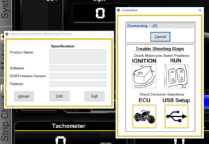
Software and PC Testing Method These tests are intended to isolate issues between the VCM and the PC.
For each of the following steps, you will click
 and then click ‘Test’.
If the computer is able to pull information from the VCM, the boxes will fill with information. This means the PC to VCM communication is fine and you can move on to testing the motorcycle side of the connection. If you receive the troubleshooting screen for longer than 10 seconds proceed to the next step in the list of tests.
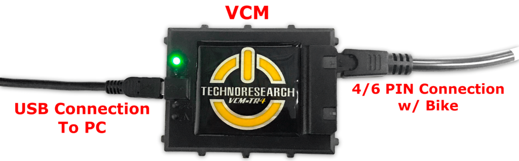
- A. Disconnect any connection to the bike. The VCM can be powered by the data port of the bike OR the USB. Connecting the VCM to only the PC should result in a green light, indicating power from the PC USB port. TEST the VCM connection. (see "Software and PC Testing Method" above)
- B. Try a different USB port on PC and a different USB cable. TEST the VCM connection. (see "Software and PC Testing Method" above)
-
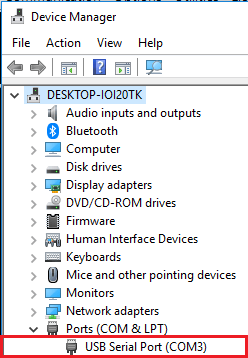
C. Make sure VCM is showing as connected in the COM Ports in the device manager. If it is not, unplug the USB and look for changes in the device manager. Restarting the computer can often trigger windows or device driver updates that were pending. After a restart, TEST the VCM connection. (see "Software and PC Testing Method" above)
-
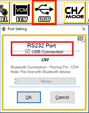
D. Make sure USB Connection is selected. This is selected by default, but if it is not, check the box and TEST the VCM connection. (see "Software and PC Testing Method" above)
- If still unable to get a connection with VCM following these steps, contact TechnoResearch Support.
- Remove all connections to the PC. Plug VCM into the motorcycle only. With the key set to IGN and Switch to "Run" there should be a green light on the VCM, indicating that the VCM is getting power from the data port of the motorcycle. Throughout the following steps, regularly check the VCM for the presence or absence of this green light.
- If using extension cable, try connecting without the extension cable. Connection with or without the extension cable should give the same results, if not please jump to the 3. VCM Connection section below.
- If not using extension cable, try connecting with the extension cable. Connection with or without the extension cable should give the same results, if not please jump to the 3. VCM Connection section below.
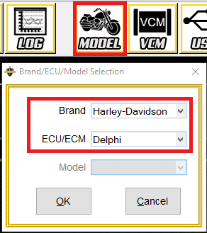
- The software does not automatically detect ECU types. It is important to make sure the proper Brand/ECU is selected in the software. Most common ECU is Delphi. So if you are working with another ECU type (or the last bike was different), this step is often missed. There is a reminder to check this on the popup trouble shooting window.
- Make sure motorcycle’s security is disarmed when attempting to connect to it. Newer motorcycles will not power any modules (or the data port) when armed. Security light flashing at a 2.5 second interval means the bike is armed and your connectivity options will be limited. See Common Jobs for more details.
- If the motorcycle has aftermarket gauges, temporarily unplug them. Some gauges cause interruptions in communication. This is a fault in the gauge design/engineering. Sometimes its necessary to remove the component that may be causing the disruption to confirm it.
- If the motorcycle has a piggy back tuner, temporarily unplug it. Some aftermarket passthrough systems cause interruptions or distortions in normal communication. Sometimes its necessary to remove the component that may be causing the disruption to confirm it.
- Make sure the motorcycle is giving off power (fuel pump kicks on, fuses aren’t bad, etc.). The absence of a fuel pump cycle is a great indicator of a problem. Taking special note of its presence or absence on an IGN cycle can help you isolate where a problem is originating.
- Make sure you’re receiving voltage at the motorcycle’s diagnostic connector even though the battery reads 12v.
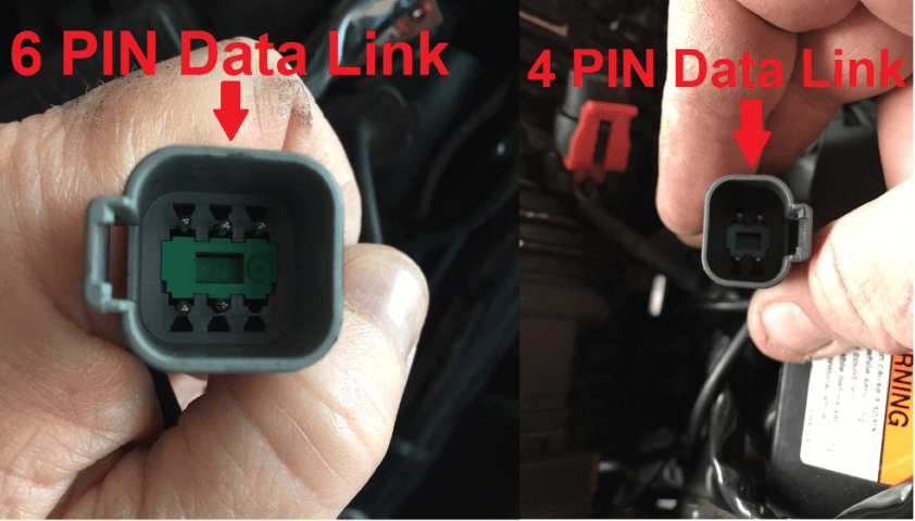
- 6 PIN Motorcycle – PIN 2 is Ground / PIN 5 is Power
- 4 PIN Motorcycle – PIN 2 is Ground / PIN 4 is Power
- Testing the tool on a similar year/model can also save a lot of time. If the tool connects normally on a similar year/model, focus more attention on the specifics of the motorcycle that might cause the issue. If the issues persist across multiple motorcycles, focus more attention on the tool side of things.
-
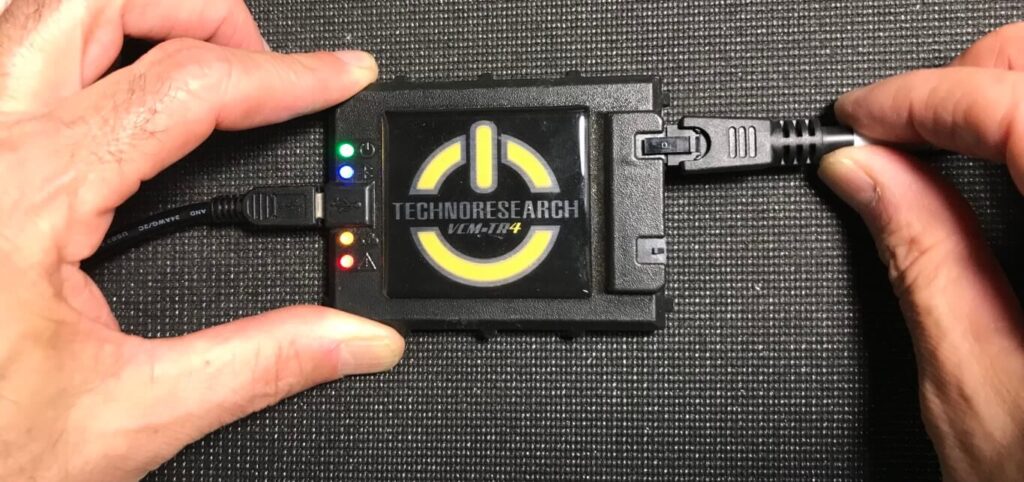
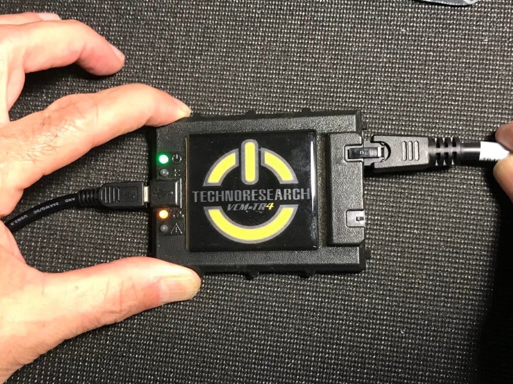
Wiggle and gently bend the connections going into the VCM. If you see all LEDs (see picture) light up there may be an issue with the contacts in the wiring. When testing this, try with and without the extension cable and note any differences. Most commonly, the reason this is happening is because the Pins or Contacts inside the smaller 6 position connector have openned up and are not making a positive contact. Doing the following steps can improve the connectivity of the contacts.
-
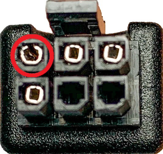
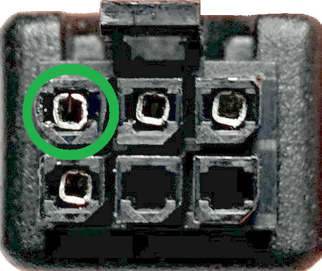
Look closely at the PINs on the cable and try to determine which one is loose or more open. Sometimes after plugging and unplugging this cable overtime, the PIN rings become loose causing intermittent connection issues. Circled in red, you can see the pin that is more open than the others. This is what we want to fix.
-
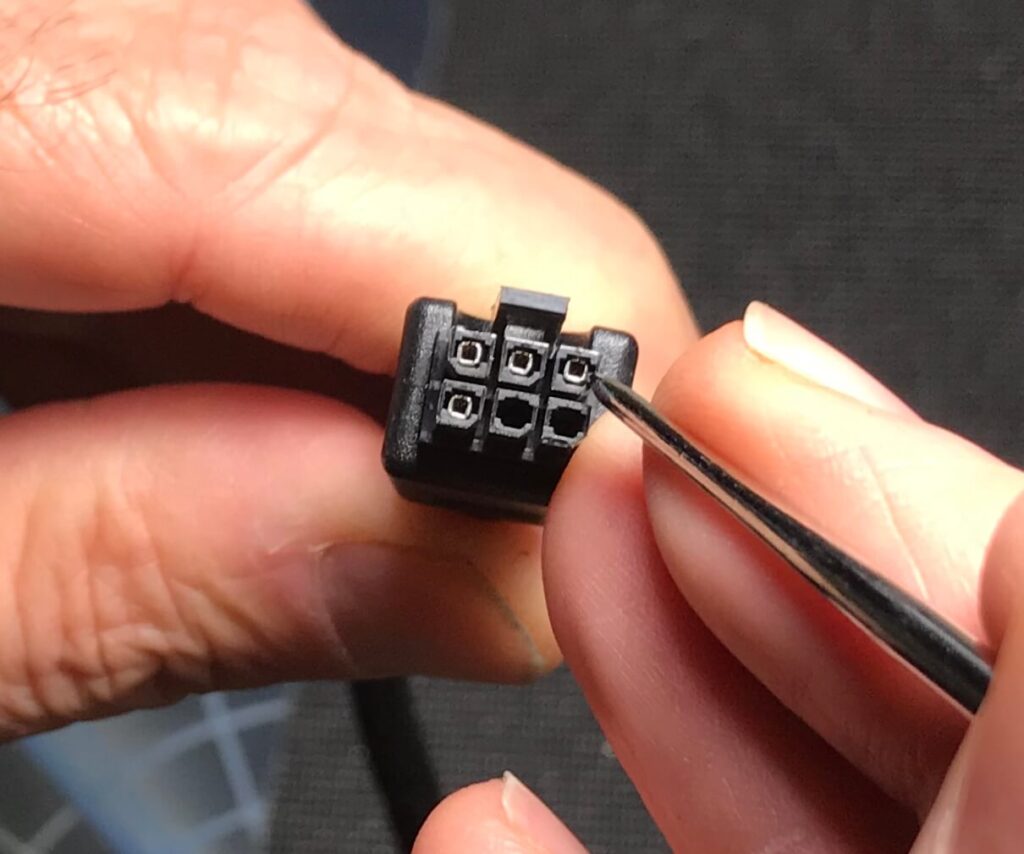
Take a small tool from around the shop (i.e. pick/Pin/Needle) and try to push the metal of the contact/pin back together so it is more closed.
-
Your cable should now look like the picture below (circled in green).
-
Now, plug the cable back in to the VCM, and when you wiggle the cable you should only see the green and, possibly, the yellow LED light up.
-
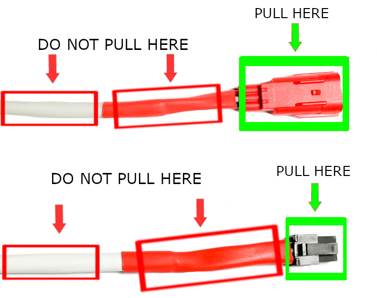
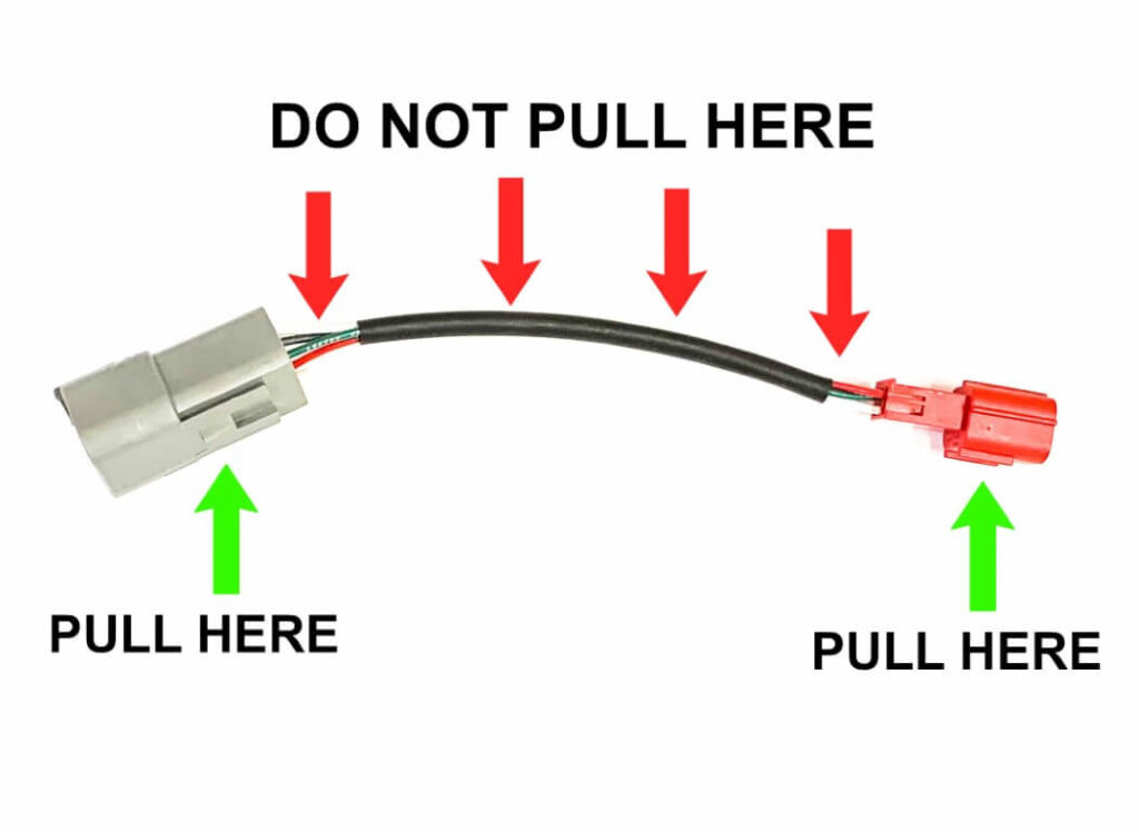
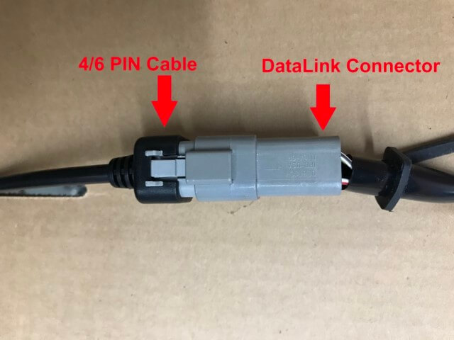
When using the new 2021 HD Cables, make sure you do not damage the wires going into the connectors. When connecting or disconnecting the cable only pull on the areas designated below.
-
If you have followed the instructions above to make sure that all the contacts/pins are healthy, checking the health of the motocycle data port connection. 4 position data ports will generally only have 3 wires/positions used (power, ground, and serial data). 6 position data ports vary, but we primarly care about the wires and contacts for: power, ground, CAN H, and CAN L.
-
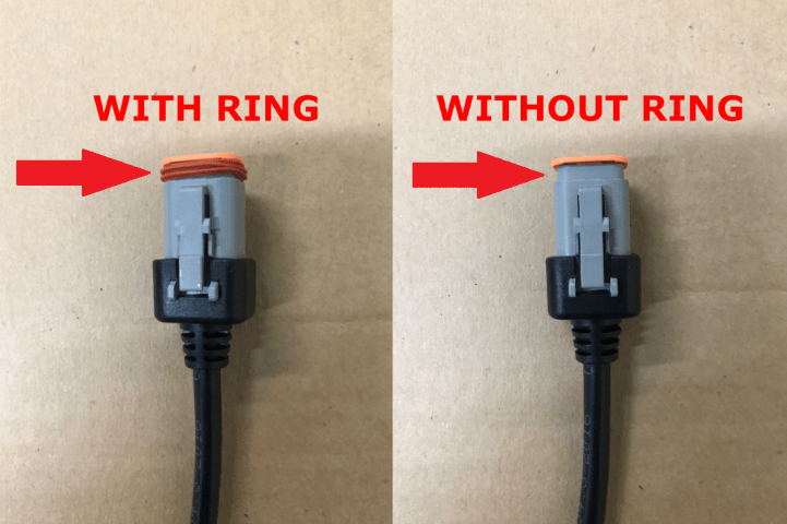
When receiving the 4 and 6 PIN cables they come with a dark orange rubber ring around the end of the connector. This ring is used to act as a water tight seal for the connection to the bike. This ring is "optional" during light typical tool usage.
-
C. Removing the orange rubber ring and plug the 4/6 PIN cable back in to the data link connector (pictured below) on the bike. Make sure that it makes full contact. The latching mechanism usually clicks into place once fully inserted.
-
It is not uncommon for the data link connection (motorcycle) to be damaged in some way. If you suspect this might be possible, check that the pins are seated correctly and that the wires are still attached to the pins. A very simple way of doing this is pushing and pulling gently on each wire. Pushing, you may feel a contact click into place (solving that issue). Pulling, you may find a wire comes right out of the connector because it wasnt connected to the contact anymore.
- If you having issues flashing, double check to make sure you have a secure connection for internet access.
- You can try temporarly disabling your internet firewall, as sometimes the firewall will block the connection of the flash from reaching our servers.
- If you are still experiencing issues, try connecting your laptop/PC to a mobile hotspot and attempt the flash again.