Table of Contents
- DirectLink Introduction
- DirectLink Main Features
- How To Setup TR4 System
- About This Manual
- Troubleshooting
- TRo2/o2 Sensors/Rivnut Installation
- O2 Sensor Installation Kit Lite
- ECU Tuning Compatibility
- All TechnoResearch Cables
- Tuning Victory® Motorcycle
- Licensing
- 1 Setup and Installation
- 1.1 Where To Get The Software
- 1.2 Install Direct Link Flash Tuner
- 1.3 Run Direct Link Flash Tuner
- 1.4 Connect USB Cable
- 1.5 Power Up The Direct Link Flash Tuner
- 1.6 Power Up To Automatically Install Drivers
- 1.7 Update The Software
- 1.8 Confirm Com Port For Communication
- 1.9 Troubleshooting Com Port Issues
- 2. Toolbar Menu and Icon Descriptions
- 3. Direct Link – Key Features
- 4. Direct Link – Important Tables
- 5. Program the Calibration into the ECU
- 6. How to Save the Modified Calibration
- 7. How to Change Units and Colors
- 8. Monitor Real-Time Data
(Gauges/Meter Display) - 9. Monitor Real-Time Data
(Strip Chart/Meter Display) - 10. Auto-Mapping
- 11. Common Issues and
Possible Solutions - Glossary
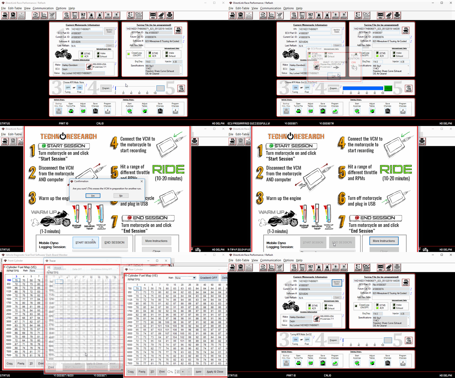
10.3 Logging Data with Mobile Dyno
Select the 'Channels/Mode' button. Choose 'Default'. The software will not continue if these channels are not selected.
Select the Auto Map icon.
Select 'Mobile Dyno' and click 'OK'.
Turn the ignition switch to 'IGNITION' and switch the run switch to 'RUN'.

 Click 'Begin' on the Mobile Dyno panel.
 A prompt will ask to configure the VCM. Select 'Yes'. All previously recorded data will be erased from the VCM. This will not affect any downloaded log files stored on the computer.
Unplug the VCM from the computer and the motorcycle (the VCM's power source). The next time the VCM gets power, it will begin recording.
When ready to ride, connect the VCM to the motorcycle diagnostics port. An LED on the VCM will blink, signifying that it is recording.
- VCM-TR1 will log up to ~15 minutes
- VCM-TR3/VCM-TR4 will log for hours
Turn the ignition switch to 'IGNITION' and switch the run switch to 'RUN'.
Select 'End Session' on the Mobile Dyno panel.

The log file will automatically download and then load.
Once the logged data is displayed, click 'Create Map' to instruct Direct Link to review the data and suggest changes to the VE. These changes seek to reconcile the Desired AFR with the Measured AFR by adjusting the volumetric efficiency of the engine at points of disparity.
Choose the tables to be modified and the O2 sensors that were used. 'External O2' should be selected when an add-on sensor tool is connected to the VCM and configured in the software. 'Motorcycle O2' should be selected only if the motorcycle is provisioned with stock sensors and an external sensor option is not available.
A simulation tracer will animate. As data was collected by the system, there will be a report of the information collected:- Counts || Desired AFR
- Front AFR || Rear AFR
- Counts: The number of samples gathered and stored for that location on the RPM vs. TPS or RPM vs. MAP tables.
- Desired AFR: The air to fuel ratio that was programmed to the ECU by the Program function. The tables are either RPM vs. TPS or RPM vs. MAP. The programmed values can be reviewed by opening the AFR table of the relevant calibration file.
- Front AFR: The air to fuel ratio that was actually measured by the O2 sensor monitoring the front cylinder.
- Rear AFR: The air to fuel ratio that was actually measured by the O2 sensor monitoring the rear cylinder.


 ).
).Now go back to the re-flash screen (
 ) and program the new calibration to the ECU.
NOTE: Make sure to BACKUP the original calibration so the motorcycle can be restored back to the original programming if desired.
